If you have been following along with this tutorial series you should have a working electronic prototype with the necessary code to turn on your TV and signal an external messaging queue to later extend the functionality of your switch using a Raspberry Pi or other internet enabled device.
In this final part of the tutorial series I will conclude with the assembly. This I found to be the most time consuming step and where I most often had to go back to the “drawing board”.
It is worth noting that the original files posted by Netflix are in a very awkward format. They seem to have been modelled in SolidWorks 2016, and unless you have a small fortune or happen to work with this product you will be unable to open these files. Fortunately my brother is a product designer and uses this particular version at his place of employment. I have had him edit the models to accomodate my own design changes and export them in a much more compatible format. The models can be found here.
Chassis and Backplate
The chasis will house the electronics from part 1 preventing bits from rattling around when we finally put everything together. You can build this from any material that you like but I opted for plastic. More specifically I had this part 3D printed in Polylactic Acid (PLA) biodegradable thermoplastic with a 100 micron layer height. Since I do not yet own a 3D printer I had this printed though the 3D Hubs service. The turnaround time can vary depending upon the local printing house you choose but I received a very professional, good quality print that I was very happy with.
I used the same service to print the backplate that will keep the chassis within the outer enclosure. You can get a copy of these printed yourself using this quick link however you are limited to the filament colour options and the printing house. Instead I’d clone the repo linked to above and manually submit the print job to 3D Hubs.
Enclosure
The enclosure envelops all the circuitry and the chassis, having the backplate securely fasten to its rear end. It is this part that gives the switch it’s finished look. I had originally intended to get this made from solid Oak and have it milled using a CNC milling machine. There are a few online services where you can have this made, operating similarly to 3DHubs, however everyone I contacted ignored my requests. So as a backup plan I had this printed too from PLA through 3DHubs.
For reference the site I attempted to use was Fabhub, a global network of professional fabricators making digital designs, on demand, all over the world. You may have more luck than I did but it would appear the order size is too small for any of the fabricators to deem worth their time.
This design almost mirrors that which was originally put together by the Netflix team. I have merged the logo and the chassis into one solid piece, and I have lengthened the recess under the logo to accommodate the LED Backlight.
Assembly
Due to the physical dimensions of the enclosure, assembly is no easy feat. First and foremost there are going to be a lot of wires living inside this box. I first attempted soldering each of the LEDs to their respective resistors, transistors and wires essentially making many little circuits that I could piece together.
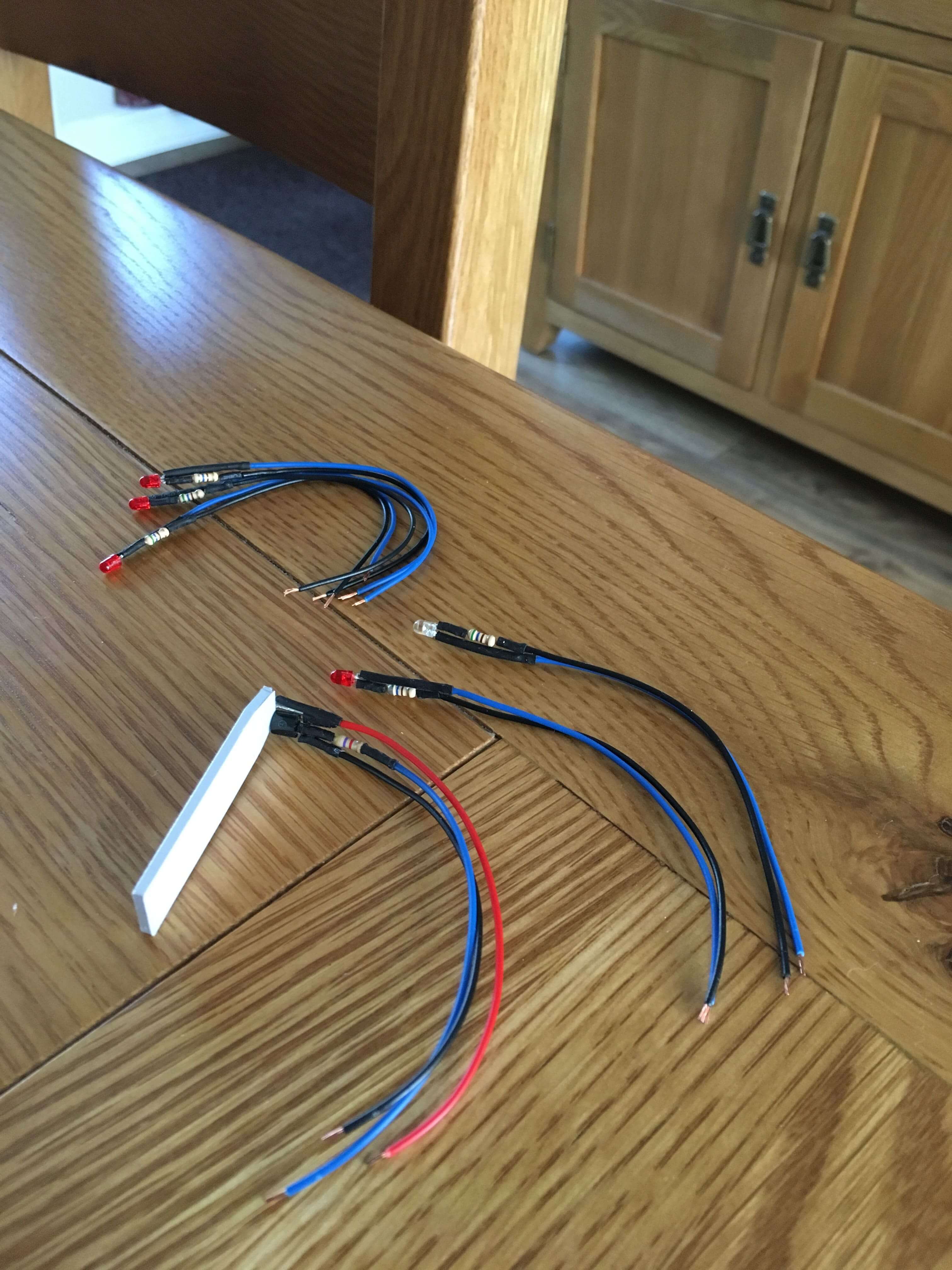
Quickly realising this was far too fiddly I instead opted to create my own PCB for the lighting array that comprises of the 5 indicator lights and the LED Backlight. Although this has not reduced the number of wires by a lot, it allows me to securely fasten down all of the lights to the enclosure and have a neat block of wires extending from the board to the Spark Photon.
I have uploaded the gerber files to OSH Park where they will print the exact same board for you for around £8 (for 3 boards - minimum order). This is incredibly cheap and will definitely mitigate a lot of frustration whilst assembling.
![]()
After receiving the boards I used a technique called hotplate reflow to attach some surface mount resistors I had lying around. These are the same value resistors as in the prototype but just far more compact as to make the electronics take up as little room as possible.
As for everything else it is a matter of following the prototype we made in a previous article and hooking it up to both the power supplied through the LiPo battery and the Spark Photon development board.
Conclusion
Finally having come to the end of this tutorial series you should have created your own Netflix switch capable of controlling your TV and potentially sending message to a remote message broker.
In future I intend to revisit making the enclosure out of wood as I feel it will give it a far better finish, but until then I am happy with the results.